9 Types of Drag
Tsunami Air • • Reading time: 12 min
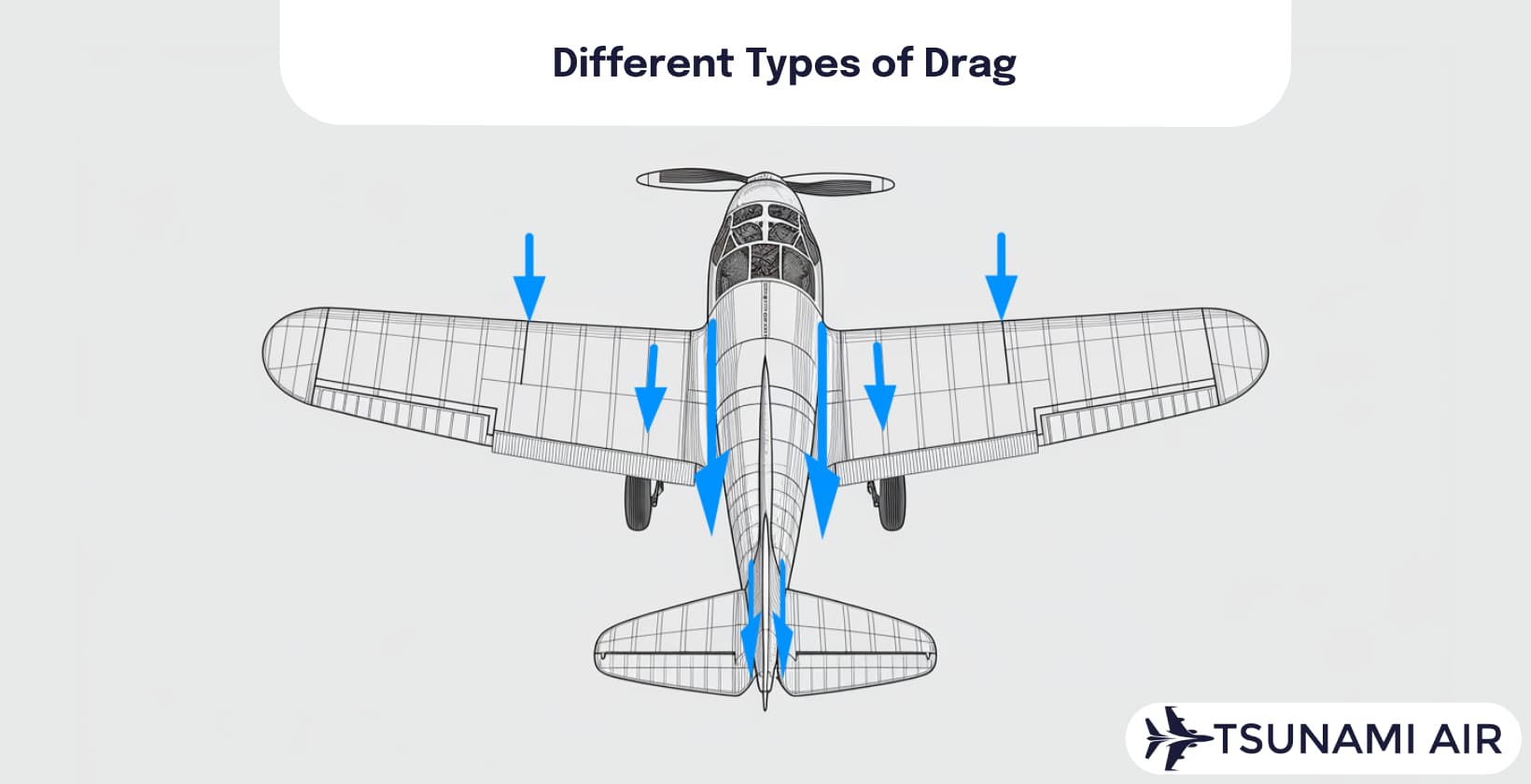
Drag is the force of resistance experienced by an object moving through a fluid, air, or water. Drag affects
aircraft performance and efficiency during flight. Drag relates to factors including air density, velocity, and
object shape. Drag manifests in forms, with nine distinct types identified. Learn about drag's force, resistance,
air interaction, aircraft impact, wave generation, and types. Discover how drag influences aerodynamics and vehicle
design across applications.
Parasite drag is the drag produced by all non-lifting components of an
aircraft. Parasite drag consists of non-lifting components including skin friction drag, form drag, and interference
drag. Skin friction drag results from friction between air and aircraft surfaces, influenced by surface texture,
viscosity, and boundary layer characteristics. Form drag is caused by aircraft shape disrupting airflow, affected by
flow separation, frontal area, and shape. Interference drag occurs when airflow is disrupted by intersecting
surfaces or protruding components, increased by airflow interference and unit junctions.
Induced drag arises from lift generation and will not be eliminated while wings generate lift. Wave drag is the resistance occurring at high speeds due to shock wave formation, becoming a factor in transonic and supersonic flight regimes. Profile drag is the drag acting on aircraft due to shape and surface characteristics, consisting of form drag and skin friction drag. Cooling drag is the drag force caused by the aircraft cooling system, accounting for up to 15% of drag in engine piston aircraft. Trim drag is the drag caused by control surface deflections, with a trim drag coefficient ranging from 0.02 to 0.05.
1. Parasite Drag
Parasite drag is the drag produced by all non-lifting components of an aircraft. Parasite drag consists of three
components: skin friction drag, form drag, and interference drag. Skin friction drag results from friction between
air and aircraft surfaces during movement. Surface texture, viscosity, and boundary layer characteristics relate to
skin friction drag on aircraft. Form drag is caused by the shape and form of the aircraft disrupting the airflow.
Flow separation, frontal area, and shape influence form drag on aircraft. Interference drag occurs when airflow is
disrupted by intersecting surfaces or protruding components. Airflow interference, component junctions, and
interactions between components increase interference drag on aircraft.
Parasite drag increases with the
square of airspeed and increased surface area exposed to airflow. Drag coefficient measures drag experienced by
aircraft. Drag area represents the product of the drag coefficient and the reference area. Force and friction in
aerodynamics play roles in determining the magnitude of parasite drag. Parasite drag becomes substantial at higher
speeds on aircraft. Total drag is the sum of parasite and induced drag on aircraft. Lower drag coefficient values
indicate better aerodynamic efficiency on aircraft.
2. Skin Friction Drag
Skin friction drag is a constituent of parasite drag arising from viscous interaction between moving objects and
surrounding fluids. Viscosity of fluids causes skin friction drag by creating shear stresses on object surfaces. The
no-slip condition ensures zero fluid velocity at surfaces, generating velocity gradients in boundary layers. Skin
friction drag depends on surface roughness of objects; smoother surfaces reduce drag while rougher surfaces increase
it due to higher shear stress.
Laminar flow characterizes flow over objects with smooth, parallel layers.
Turbulent flow follows laminar flow, amplifying mixing in fluids and increasing drag due to irregular patterns.
Reynolds Number influences the laminar-turbulent transition, representing the ratio of inertial to viscous forces.
Reynolds Numbers favor turbulent flow, leading to increased drag.
The skin friction coefficient
quantifies drag force relative to dynamic pressure, varying with Reynolds Number and surface conditions. Surface
irregularities like rivets and dirt increase skin friction drag by disrupting airflow over surfaces. Skin friction
drag accounts for 45% of drag in subsonic aircraft, impacting aerodynamic design and performance
optimization.
Viscosity measures fluid resistance to flow; viscosity increases drag. Surface roughness
enhances turbulent flow, which increases drag compared to smooth surfaces. The Reynolds Number indicates the ratio
of inertial to viscous forces, with higher values leading to turbulent flow and increased drag. Laminar drag occurs
in ordered flow regimes with lower shear stress, while turbulent drag occurs in chaotic flow regimes with mixing and
higher shear stress.
3. Form Drag
Form drag is resistance caused by an object's shape disrupting fluid flow. Shape dependence and irregularity play a
critical part in form drag. Bluff bodies with non-streamlined shapes experience form drag due to increased flow
separation. The drag coefficient quantifies the shape factor's influence on aerodynamic resistance. Form drag
coefficient measures the shape-dependent unit of total drag.
Flow separation and pressure distribution
are key mechanisms in form drag generation. Boundary layer separation occurs at the adverse pressure gradient, near
the widest part of an object. The separation point marks where the flow detaches from the surface, creating a
low-pressure wake. Pressure distribution around the object determines the magnitude of form drag. Pressure drag,
another term for form drag, results from the pressure differential between the front and rear
surfaces.
Wake formation contributes to form drag effects. Low pressure in the wake region creates a
suction force opposing forward motion. Wake recirculation and turbulence increase energy dissipation, amplifying
drag. The wake's size and intensity correlate with the amount of form drag experienced by the
object.
Vortex shedding is a phenomenon in form drag. Alternating vortices shed from the object's sides
at an oscillation frequency. The Strouhal number relates this shedding frequency to the object's characteristic
length and flow velocity. Vortex shedding contributes to form drag by creating pressure fluctuations and increasing
wake turbulence.
The dimensionless drag coefficient represents overall aerodynamic resistance, including
form drag contributions. Form drag force is calculated using the drag equation, which incorporates factors including
fluid density, velocity, and frontal area. Pressure drag, measured through pressure differences, forms a portion of
total form drag.
4. Interference Drag
Interference drag occurs when airflows around aircraft components interact and interfere with each other. Airflow
interactions create flows, wakes, and localized shock waves, leading to increased drag beyond what individual
components produce.
Wing-fuselage junctions are primary locations of interference drag. Slower-moving
fuselage air interacts with wing airflow, creating turbulence and drag at the junction. Engine nacelle integration
with wings or fuselages causes interference drag through streamlining. Tail surface discontinuities and sharp angles
disrupt airflow, resulting in interference drag.
Interference drag manifests as flow separation and
increased pressure gradients. Flow separation enhances drag by 15-20% in poorly designed junctions. Increased
pressure gradients amplify drag by up to 30% in some cases. Smooth transitions between components mitigate
interference drag effects by up to 50%.
Fairings and fillets reduce interference drag at wing-fuselage
junctions by 25-40%. Curved surfaces and minimized geometric discontinuities decrease interference drag by 30-50%.
Strut and pylon protrusions create discontinuities, increasing interference drag by 10-15% if not properly
addressed.
Aircraft designers implement strategies to minimize interference drag for refined aerodynamic
efficiency. Fuselage blending techniques reduce interference drag by 20-30%. Wing airfoil geometry optimization
decreases interference effects by 15-25%. Fairing and streamlining of intersecting surfaces reduces interference
drag by 40-60%.
5. Induced Drag
Induced drag constitutes a type of drag arising as a consequence of generating lift. Lift production links to induced
drag and cannot be eliminated while wings generate lift. Wingtip vortices cause induced drag due to the pressure
difference between wing surfaces.
Lift generation creates downwash, deflecting airflow downward behind
the wing. Wing tip vortex formation dissipates energy and contributes to induced drag. Pressure distribution across
the wing surface results in flow deflection at the wingtips. Vorticity in the wake formation increases induced
drag.
Lift coefficient affects induced drag magnitude. Aspect ratio geometry is a factor in determining
induced drag. Span-to-chord ratio influences the strength of wingtip vortices. Wing efficiency factor accounts for
deviations from ideal lift distribution.
Induced drag coefficient equals C_L^2 / (π * AR * e), where C_L
is lift coefficient, AR is aspect ratio, and e is span efficiency factor. Induced drag ratio decreases with
increasing airspeed squared. Induced drag magnitude depends on flight conditions like angle of attack and
velocity.
Induced drag impacts aerodynamic efficiency by increasing total drag force. Induced drag
resistance reduces aircraft performance and affects climb rate, range, and fuel consumption.
6. Wave Drag
Wave drag is a type of aerodynamic resistance occurring at high speeds due to shock wave formation. Shock waves form
when aircraft approach or exceed the speed of sound, creating pressure discontinuities in the airflow. Wave drag
becomes a factor in transonic and supersonic flight regimes, between Mach 0.8 and 1.2.
Shock waves result
from airflow compression and acceleration over curved surfaces. The air cannot move out of the way at high speeds,
leading to pressure buildup and discontinuities. Supersonic aircraft experience a Mach cone, which produces the
sonic boom. Wave drag increases as aircraft approach the critical Mach number, a phenomenon known as drag
divergence.
Compressibility effects play a part in wave drag. Density variations and pressure
fluctuations become considerable at high speeds, contributing to the formation of shock waves. The interaction
between shock waves and the boundary layer causes flow separation and instability, augmenting drag.
Wave
drag depends on factors, including Mach number, angle of attack, and airfoil shape. The coefficient of wave drag
varies with these parameters, affecting the overall aerodynamic performance. For a flat plate airfoil, the wave drag
coefficient is given by a formula relating to the Mach number and thickness-to-chord ratio.
Swept wings,
supercritical airfoils, and fuselage modeling help reduce shock wave formation and mitigate wave drag. The Whitcomb
area rule is a design principle used to minimize wave drag by optimizing the aircraft's cross-sectional area
distribution.
7. Profile Drag
Profile drag is a type of drag acting on an aircraft due to its shape and surface characteristics. Profile drag
consists of two elements: form drag and skin friction drag. Form drag results from the pressure distribution around
the aircraft's body, influenced by its frontal area and geometric configuration. Skin friction drag arises from the
interaction between air molecules and the aircraft's surface, affected by surface roughness and wetted
area.
Flow separation occurs when airflow detaches from the aircraft's surface, at the separation point
where pressure gradients exist. The airfoil's camber and chord impact flow separation and profile drag. Increasing
the angle of attack leads to greater flow separation, resulting in higher profile drag.
Thicker boundary
layers and increased turbulence contribute to higher skin friction drag. The profile drag coefficient quantifies the
drag force experienced by an airfoil. Profile drag area represents the equivalent flat plate area that produces drag
equal to the actual aircraft shape.
Airfoil design focuses on minimizing profile drag through
consideration of camber, chord, and angle of attack. Streamlined shapes reduce form drag by maintaining pressure
gradients and delaying flow separation. Smooth surfaces and minimized wetted areas help decrease skin friction drag.
Profile drag force increases with the square of airspeed, making it a factor in aircraft performance at higher
velocities.
8. Cooling Drag
Cooling drag is a drag force caused by the aircraft's cooling system. Propeller-driven aircraft experience cooling
drag due to their air-cooled engines. Cooling drag accounts for up to 15% of drag in single-engine piston
aircraft.
Engine heat generation necessitates cooling systems to maintain safe operating temperatures.
Air-cooled engines require 6 to 12 inH2O pressure drop to force air through the cooling system. Pressure drop
consumes up to 10% of engine horsepower, contributing to cooling drag.
Radiators and heat exchangers play
roles in managing thermal loads. Radiator surface area and fin density impact heat exchange efficiency and pressure
drop across the system. Fin density minimizes drag while amplifying heat dissipation.
Cooling ducts'
geometry and cross-section influence airflow characteristics. Ducted radiator inlets reduce turbulence and drag by
smoothing airflow paths. Upgrading the duct area enhances airflow capacity, reducing cooling system pressure
drop.
Airflow velocity, pressure, and density affect cooling drag. Higher velocities increase cooling
efficiency but increase drag. Airflow density influences heat absorption capacity, impacting the cooling system's
effectiveness.
Jet engines, while producing heat, rely on different cooling methods. Jet engines use
self-generated airflow for cooling, managing operating temperatures through cooling systems. Turbine cooling in jet
engines requires design to control heat production without excessive drag penalties.
Optimization
strategies focus on refining radiator design, heat exchanger efficiency, and cooling duct configuration. Designed
radiators enhance heat exchange while reducing drag. Efficient cooling systems minimize energy loss and drag by
guaranteeing smooth airflow over the engine.
9. Trim Drag
Trim drag is additional aerodynamic drag caused by control surface deflections to maintain aircraft equilibrium.
Aircraft configuration and weight distribution impact trim drag. Center of gravity balance affects the moment arm
and static stability of the aircraft. Flight control surfaces play a part in managing trim drag. The horizontal
stabilizer provides stability support, while elevator deflection angle influences pitch control. Trim tabs on
control surfaces allow for deflection adjustment to reduce control forces.
The trim drag coefficient
ranges from 0.02 to 0.05, depending on aircraft design. Trim drag force is a part of parasite drag, increasing drag
on the aircraft. Pitch control and stability compensation require management of trim drag. Control effectiveness
relies on balancing moments to maintain aircraft equilibrium. Trim drag affects aircraft performance, influencing
fuel efficiency and flight characteristics.
Elevator pitch influence is a primary factor in trim drag
creation. Downward elevator deflection generates increased drag, while upward deflection reduces drag but requires
more force for pitch stability. The horizontal stabilizer acts as a lifting body at subsonic speeds, contributing to
trim drag through its control deflection. Static stability ensures the aircraft returns to equilibrium after
disturbances, with trim drag providing the necessary restoring moment. Trim drag management optimizes weight
distribution and enhances flight efficiency.